Some four point probe electronics such as the Jandel RM3000 Test Unit have a feature in which the electronics can scan various input current choices to determine which choice of input current is most appropriate for the material being measured. Insufficient input current for a given material will result in an invalid measurement.
If an attempt is made to force too high of a current for a material that is not conductive enough for the selected current, it will be impossible to drive the current with the available voltage, in which case a lower input current will have to be used. When using a four point probe electronics set which does not have the auto-ranging feature, one can perform a relatively simple test to determine which choice of input current will be most appropriate.
First, try to force a relatively low input current to see if it can be passed at all. If not, try the lowest available. If that cannot be forced, then either the material is too insulating for the particular measurement electronics, or there may be a problem with the probe tips specifications (tips that are too sharp, too blunt, or an incorrect choice of contact pressure), or the tips may be damaged. Some materials are more sensitive to choice of probe tip specifications than others. The Jandel four point probe electronics units will give a “contact error” message if the selected input current cannot be forced.
Once a given current can be successfully passed, check the voltage value read between the center two probes. With the Jandel models, you can press a button to toggle from displaying the sheet resistance value expressed in ohms-per-square to instead displaying millivolts. To check the voltage value, the electronics should be in the mV mode instead of the ohms-per-square mode, otherwise the + and – values may not be displayed. The button which toggles between reading out in mV and ohms-per-square is labeled with the ohms/square symbol. The Jandel models have buttons labeled FWD (forward) and REV (reverse) which allow the direction of the input current to be driven either forward (in relation to the voltage reading probes) or in reverse.
The RM3000 and HM21 meters will show an “F” or an “R” on the display when the forward (FWD) and reverse (REV) buttons are pressed while in the ohms/square mode, however older models do not have that feature. The millivolt values (or ohms-per-square values if using the RM3000 or HM21) that are displayed when the current is driven forward and then reverse should be similar values, except the reversed current voltage value will be a negative number if in the mV mode. There are exceptions to this rule: 1) very conductive materials do not reverse well due to the very small voltage signals, 2) photo voltaic materials do not reverse well unless they are protected from light during the measurement. Poor correlation between the millivolt values when the current is driven forward and reverse can often be remedied by increasing the input current or correcting a contact problem that can exist due to the wrong choice of probe tip specifications. Zeroing the meter while the probes are in contact is another way to improve the forward and reverse current, voltage values.
A four point probe user wrote: “My samples are dopant wafers, p type, with nominal resistivity 0.002 to 0.004 ohm-cm. I need to know the values more accurately and I’m using the RM3 [predecessor to the current Jandel RM3000] and a hand held probe. I set the RM3 at a set current of 99mA per your suggestion and set the sensitivity to ‘high’. The results for 14 samples are as attached in the Excel spreadsheet. What I found was that there was quite a difference between the forward and reverse voltages, typically say 0.43mV forward and 0.32mV reverse. The resistivity calculated from Ro = 4.532 x w x V/I x F(w/s) using the average of the forward and reverse voltages comes out where I would expect it to be based on the nominal resistivity. I think that the difference between forward and backward voltage can be explained by the importance of surface contact resistance effects where the sample is very low resistivity. So my question is simply to ask if it is valid simply to use the average value of voltage in this calculation? Are we operating the RM3 at its limit and what accuracy would you expect in this case?”
Jandel wrote: “Yes, it is valid to average the readings of the forward and reverse results. We always recommend taking a reading in both directions. It may be helpful to press the ‘zero’ button which can help reduce or remove an offset within the unit. It is possible that there is an effect of contact resistance as you say – is there any possibility that the samples are light sensitive? This can also produce an offset. Yes, the unit is operating just within its limits, but I would expect the electronics to be producing results correct to within 0.3 – 0.5%, especially if the readings are stable.”
Jandel wrote: “Ideally a measured voltage of 10mV to 100mV should be aimed for, although this is not always possible.”
Some of the reasons that the voltage values may not correlate well when the current is reversed (keeping in mind that with the current reversed, the voltage reading will be a negative value) include:
- Insufficient input current (try using a higher current, but normally do not exceed 100mA)
- Poor ohmic contact (worn or broken probe tips, or tips not suitable for the material)
- The materials are photo sensitive and are not protected from light during the measurement. Pete Clark of Jandel Engineering wrote, “I have some comments on light sensitivity as more and more people are measuring light sensitive Si these days. There are a few signs that samples are light sensitive, as follows:
- Readings at the same point may differ. i.e. if you measure a point, raise then lower the probe, measure again the readings can be quite different (maybe 10%). We would not expect to see this on standard samples
- Readings do not increase uniformly with current. I.e. if 1mA yielded 10mV one would expect 10mA to yield 100mV – this does not happen on light sensitive samples which are exposed to light at the time of measurement
- There can be large differences between forward and reverse readings, especially if small (sub 10mV) readings are being made.
- The material is very conductive in which case the voltage values are very small and a close correlation is not possible.
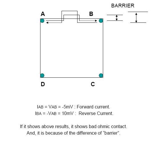
Bad ohmic contact can be detected by reversing the current and comparing the voltage values between the forward and reverse current values (square array Hall measurement shown):
Four-Point-Probes is a division of Bridge Technology. To request further information please call Bridge Technology at (480) 219-9007 or send e-mail to Joshua Bridge at: sales@bridgetec.com